-
Entry date 24.07.2025
Condition monitoring at HUSUM WIND 2025

-
Entry date 16.07.2025
Condition monitoring saves system operators a lot of money

-
Entry date 27.01.2025
Drum coupling monitoring - Automatic condition monitoring on cranes

-
Entry date 18.10.2024
Condition Monitoring and Artificial Intelligence

-
Entry date 15.12.2023
Condition monitoring at maintenance Dortmund on February 21st and 22nd, 2024

Mills in Cement Plants, Power Plants and Mines
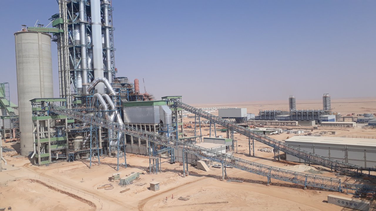
In industry, there are different types of mills, e.g. the vertical mill, the ball mill and roller mill. Usually mills are powered by one or more electric motors. For speed reduction one or more gears are used, which in turn may contain spur gear stages, bevel gear stages and planetary stages. Power is transferred to the mill via a shaft or girth gear. The waves are usually mounted on roller bearings.
But no matter what type of mill is used, the mills are typically operated around the clock. The drive powers up to a few hundred kilowatts to the doubledigit megawatt range. The throughput of ground material is correspondingly high. And usually replacement parts are not available for such large acceleration sensor at gear box machines and must be ordered and manufactured as needed. Therefore the failure of a mill entails enormous revenue losses.
An online condition monitoring system can detect irregularities at an early stage. However, also the documentation of the state after delivery and installation is often of importance. This can be achieved with an offline diagnosis. In contrast to, if there occur any problems surprisingly, the cause can be narrowed down quickly by the combination of vibration and torque measurement, possibly supplemented by the examination of the gear by visual inspection or endoscopy.
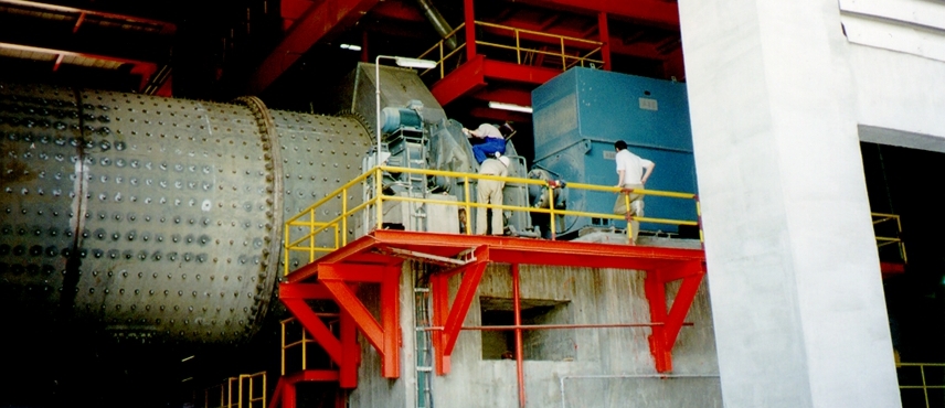
Peakanalyzer on a ball mill
This ball mill is driven by a 2,800 kW motor and a threestage helical gear unit.
Two acceleration sensors are provided on the motor, one on the drive side and one on the non drive side, radially. On the four gearbox shafts, an acceleration sensor has also been placed radially, on each side. Another acceleration sensor is installed on the transmission input shaft in the axial direction. The radially installed senors detect bearing and gear effects, the axial installed sensor is primarily intended for the detection of anomalies on the coupling.
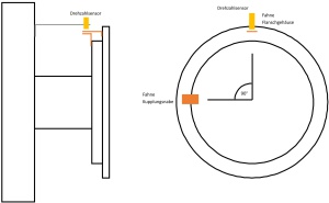
Furthermore, a speed sensor has been installed on the transmission input shaft. The knowledge of the actual speed is important for the diagnosis and the application of the order analysis.
