- Entry date 16.03.2026 Condition Monitoring – Special Offer for Wind Turbines GfM’s Peakanalyzer condition monitoring system has proven itself over many years in the monitoring...
-
Entry date 10.12.2025
Monitoring service for third-party systems using continuous online spectral analysis

-
Entry date 24.07.2025
Condition monitoring at HUSUM WIND 2025
-
Entry date 16.07.2025
Condition monitoring saves system operators a lot of money
-
Entry date 27.01.2025
Drum coupling monitoring - Automatic condition monitoring on cranes

-
WindEnergy Hamburg 2026
22.09.2026 - 25.09.2026
-
Maintenance München
08.10.2026
-
34th Wind Energy Days in Linstow
10.11.2026 - 12.11.2026
Converter Bearing Diagnosis
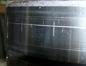
A converter is a heat-resistant container in which steel is produced at around 1,500 °C. Large converters hold over 300 tons of liquid material and are refilled approximately 50 times per day. The converter must be swiveled for loading and unloading. This is done via pins that are guided in rolling bearings. These converter bearings only occasionally perform rotational movements that are also smaller than a full revolution. At the same time, they have to absorb a large static load as well as dynamic loads caused by the production process. This can lead to damaging processes.
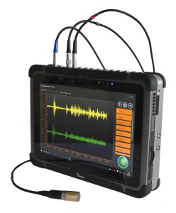
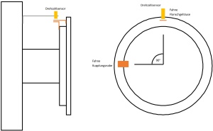
GfM has created a reliable diagnostic procedure for diagnosing converter bearings and has successfully used it several times. All that is used for this is the angle of rotation and signals from displacement sensors that measure directly on the shaft. The sensors can be retrofitted to existing systems.
The idea is that, on the one hand, a localized irregularity in the rolling bearing must also lead to a minimal movement of the shaft, which then correlates with the angle of rotation of the converter. On the other hand, wear can also be measured, which is hardly avoidable, especially on such slow-moving bearings, and which sooner or later results in a permanent change in the position of the shaft. The dynamic component of the signal to detect local bearing damage as well as the change in the static component to detect circulating damage processes are analyzed.
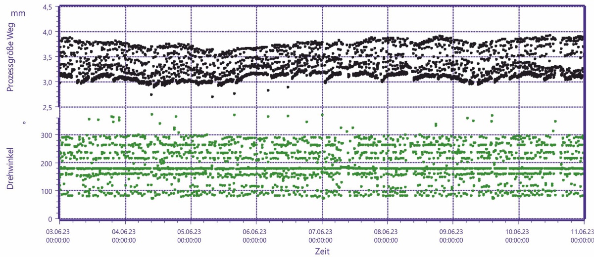
The recorded signals are further processed using tools of the statistics. A classification and the formation of long-term trends takes place. This makes it possible to detect both changes in the shaft position and damage to the converter bearings separately.
The display of the correlated signals of a displacement sensor over time (Figure 3) makes it possible to generate a trend of the damage status of the installed rolling bearings. This data can then be used to determine failure probabilities, which help to reduce unplanned downtimes on the converter.